A Piezoelectric MEMS Microphone Based on Lead Zirconate Titanate (PZT) Thin Films
Army Research Laboratory
www.dtic.mil/cgi-bin/GetTRDoc?AD...
20141123
Summery
-Piezoelectric microelectromechanical (MEMS) scale acoustic sensors have potential applications in a wide variety of applications including hearing aids, surveillance, and heart monitoring. For each of these systems and many others, the acoustic sensors must be miniaturized and have low power requirements. A piezoelectric-based microphone can provide a solution to these requirements, since it offers the ability to passively sense without the power requirements of condenser or piezoresistive
microphone counterparts.
-Miniature acoustic sensors are crucial for a wide range of military and commercial applications.
A microelectromechanical (MEMS) scale acoustic sensor can easily be implemented into a
sensor suite used for unattended remote sensing applications or as an inexpensive hearing aid for
the hearing impaired. Other potential applications include use in acoustic signal localization,
physiological monitoring, and as an integral component in a MEMS scale photoacoustic
spectrometer.
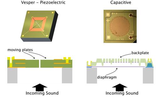
-There have been numerous efforts in developing a MEMS microphone. The three main
approaches investigated have been capacitive, piezoresistive, and piezoelectric (1-7). Most past
research has focused on complementary metal oxide semiconductor (CMOS) integration so that
on-chip amplifier circuitry can be implemented along with the microphone. Capacitive and
resistive microphones have been examined the most because of their relative ease integrating
with microelectronics. Additionally, substantial efforts have been put forth attempting to
integrate a zinc oxide (ZnO) piezoelectric microphone with CMOS (8-10).
-PZT, acoustic Sensor, MEMS, microphone
A Piezoelectric MEMS Microphone Based on Lead
Zirconate Titanate (PZT) Thin Films
by Ronald G. Polcawich
ARL-TR-3387 November 2004
Approved for public release; distribution unlimited.
NOTICES
Disclaimers
The findings in this report are not to be construed as an official Department of the Army position unless
so designated by other authorized documents.
Citation of manufacturer’s or trade names does not constitute an official endorsement or approval of the
use thereof.
Destroy this report when it is no longer needed. Do not return it to the originator.
Army Research Laboratory
Adelphi, MD 20783-1197
ARL-TR-3387 November 2004
A Piezoelectric MEMS Microphone Based on Lead
Zirconate Titanate (PZT) Thin Films
Ronald G. Polcawich
Sensors and Electron Devices Directorate, ARL
Approved for public release; distribution unlimited.
ii
REPORT DOCUMENTATION PAGE Form Approved
OMB No. 0704-0188
Public reporting burden for this collection of information is estimated to average 1 hour per response, including the time for reviewing instructions, searching existing data sources, gathering and maintaining the
data needed, and completing and reviewing the collection information. Send comments regarding this burden estimate or any other aspect of this collection of information, including suggestions for reducing the
burden, to Department of Defense, Washington Headquarters Services, Directorate for Information Operations and Reports (0704-0188), 1215 Jefferson Davis Highway, Suite 1204, Arlington, VA 22202-4302.
Respondents should be aware that notwithstanding any other provision of law, no person shall be subject to any penalty for failing to comply with a collection of information if it does not display a currently valid
OMB control number.
PLEASE DO NOT RETURN YOUR FORM TO THE ABOVE ADDRESS.
1. REPORT DATE (DD-MM-YYYY)
November 2004
2. REPORT TYPE
Final
3. DATES COVERED (From - To)
December 2002 to July 2004
5a. CONTRACT NUMBER
5b. GRANT NUMBER
4. TITLE AND SUBTITLE
A Piezoelectric MEMS Microphone Based on Lead Zirconate Titanate (PZT)
Thin Films
5c. PROGRAM ELEMENT NUMBER
5d. PROJECT NUMBER
5e. TASK NUMBER
6. AUTHOR(S)
Ronald G. Polcawich
5f. WORK UNIT NUMBER
7. PERFORMING ORGANIZATION NAME(S) AND ADDRESS(ES)
U.S. Army Research Laboratory
ATTN: AMSRD-ARL-SE-RL
2800 Powder Mill Road
Adelphi, MD 20783-1197
8. PERFORMING ORGANIZATION
REPORT NUMBER
ARL-TR-3387
10. SPONSOR/MONITOR'S ACRONYM(S)
9. SPONSORING/MONITORING AGENCY NAME(S) AND ADDRESS(ES)
U.S. Army Research Laboratory
2800 Powder Mill Road
Adelphi, MD 20783-1197
11. SPONSOR/MONITOR'S REPORT
NUMBER(S)
12. DISTRIBUTION/AVAILABILITY STATEMENT
Approved for public release; distribution unlimited.
13. SUPPLEMENTARY NOTES
14. ABSTRACT
Piezoelectric microelectromechanical (MEMS) scale acoustic sensors have potential applications in a wide variety of applications including hearing aids, surveillance, and heart monitoring. For each of these systems and many others, the acoustic sensors must be miniaturized and have low power requirements. A piezoelectric-based microphone can provide a solution to these requirements, since it offers the ability to passively sense without the power requirements of condenser or piezoresistive
microphone counterparts. This research effort reports on the design and fabrication of a piezoelectric PbZr0.52Ti0.48O3 (PZT)
based acoustic sensor. A circular clamped membrane consisting of a dielectric for structural support and a piezoelectric actuator has been fabricated on a silicon wafer via silicon deep reactive ion etching (DRIE). Sensors ranging from 500 to 2000 microns in diameter have been fabricated and characterized with the use of scanning laser Doppler vibrometry and calibrated acoustic
tone sources. The PZT sensors exhibited a sensitivity of 97.9 to 920 nV/Pa, depending on geometry.
15. SUBJECT TERMS
PZT, acoustic Sensor, MEMS, microphone
16. SECURITY CLASSIFICATION OF:
19a. NAME OF RESPONSIBLE PERSON
Ronald G. Polcawich
a. REPORT
Unclassified
b. ABSTRACT
Unclassified
c. THIS PAGE
Unclassified
17. LIMITATION
OF
ABSTRACT
UL
18. NUMBER
OF PAGES
28
19b. TELEPHONE NUMBER (Include area code)
(301) 394-1275
Standard Form 298 (Rev. 8/98)
Prescribed by ANSI Std. Z39.18
iii
Contents
List of Figures iv
List of Tables v
1. Introduction 1
2. Microphone Fabrication 3
3. Acoustic Testing 6
4. Results and Discussions 8
5. Conclusion 16
6. References 17
Distribution List 19
iv
List of Figures
Figure 1. Schematic description of a MEMS photoacoustic resonant cell. ....................................2
Figure 2. Processes for the deposition of (a) PECVD dielectrics, (b) DC magnetron sputtered
metals, and (c) sol-gel deposited PZT thin films. ......................................................................3
Figure 3. Fabrication process flow for creating a PZT membrane microphone: (a) Starting
wafer, (b) sacrificial titanium, (c) Ar ion mill of Ti/Pt/PZT/Pt, (d) PZT wet etch, (e) oxide
passivation deposition, (f) etching of passivation, (g) Ti/Au contact, (h) silicon DRIE, and
(i) front view of released PZT membrane..................................................................................4
Figure 4. Illustration of the device die, after the Bosch process, with as many as four
individual PZT microphones per die..........................................................................................6
Figure 5. Images of the acoustic test chamber used for testing the PZT microphone. (The
BNC mounts provide electrical contact to the packaged microphone whereas the acrylic
plate on top provides a connection for the acoustic tube.).........................................................7
Figure 6. Schematic representation of experimental test setup for analysis of the PZT and
calibrated B&K microphones. ..................................................................................................8
Figure 7. (a) Optical surface micrograph of a PZT membrane actuator with center 80%
electroded and (b) optical surface micrograph of a PZT actuator with outer 20%
electroded...................................................................................................................................9
Figure 8. (a) An SEM image of a silicon DRIE release, (b) SEM image of the surface profile
of a released membrane, and (c) SEM image illustrating the SiO2 passivation. .....................10
Figure 9. Laser Doppler vibrometry (LDV) results (a) mode shapes of fundamental and third
harmonic vibration and (b) frequency response from a 500-μm diameter membrane with
80% sensor coverage................................................................................................................11
Figure 10. Resonant frequency versus the inverse membrane radius confirming membrane
behavior rather than clamped plate behavior of the PZT microphones. .................................12
Figure 11. Acoustic response of a B&K and a 750-μm diameter PZT MEMS microphone
with 20% sensor coverage for (a) B&K Pistonphone 250-Hz tone at 124 dB and (b) ACO
Pacific 1-kHz tone at 104 dB. ..................................................................................................13
Figure 12. Sensitivity versus radius of microphone including both predicted values and the
amplified experimental results for the 20% and 80% coverage sensors.................................14
Figure 13. Abnormal polarization electric field hysteresis loop for a 1000-μm diameter
PZT microphone. .....................................................................................................................15
Figure 14. Optical micrograph of a 80/20 combined acoustic sensor...........................................15
v
List of Tables
Table 1. Basic performance characteristics of the three most investigated MEMS
microphones (1). ........................................................................................................................1
Table 2. ZnO (13) and PZT thin film properties and microphone sensitivity. ..............................2
vi
INTENTIONALLY LEFT BLANK.
1
1. Introduction
Miniature acoustic sensors are crucial for a wide range of military and commercial applications.
A microelectromechanical (MEMS) scale acoustic sensor can easily be implemented into a
sensor suite used for unattended remote sensing applications or as an inexpensive hearing aid for
the hearing impaired. Other potential applications include use in acoustic signal localization,
physiological monitoring, and as an integral component in a MEMS scale photoacoustic
spectrometer.
There have been numerous efforts in developing a MEMS microphone. The three main
approaches investigated have been capacitive, piezoresistive, and piezoelectric (1-7). Most past
research has focused on complementary metal oxide semiconductor (CMOS) integration so that
on-chip amplifier circuitry can be implemented along with the microphone. Capacitive and
resistive microphones have been examined the most because of their relative ease integrating
with microelectronics. Additionally, substantial efforts have been put forth attempting to
integrate a zinc oxide (ZnO) piezoelectric microphone with CMOS (8-10).
Table 1 illustrates several performance specifications for the three main microphone
technologies. A piezoelectric-based microphone can offer two main advantages: no required
input power and a wide dynamic range. A passive acoustic sensor is ideal for the low cost,
disposable sensors required by the military for remote sensing. Although the piezoelectric
sensors may be less sensitive than their capacitive and piezoresistive counterparts, they can be
very advantageous in situations not necessarily governed by sensor sensitivity. For example, in
an open environment, low frequency, 1/f noise, can dominant the spectrum and provide a noise
floor of 30 to 40 dB sound pressure level (SPL) (re 20 μPa). During the same conditions, typical
battlefield sounds can be much greater than 100 dB SPL (e.g., a brick of C4 explosive at 30 m is
165 dB and a rifle shot at the shooter’s ear is 156 dB).
Table 1. Basic performance characteristics of the three most investigated
MEMS microphones (1).
Capacitive Piezoresistive Piezoelectric
Sensitivity
(◊V/Pa)
Good
400 to 1000
Low
0.1 to 100
Medium
10 to 500
Input Power Required Required None
Dynamic
Range Narrow Relatively Wide Wide
2
For a passive piezoelectric microphone, there are several options for the thin film sensor material
including ZnO, aluminum nitride (AlN), and lead zirconate titanate (PZT). Our research focused
on developing a PZT microphone because of its large piezoelectric coefficient and low dielectric
loss compared to ZnO. The microphone was designed for use in a MEMS scale photoacoustic
spectroscopy system (11,12). The MEMS microphone was integral in the miniaturization of the
photoacoustic resonant cell allowing for improved trace gas sensing through a reduction in path
length between the photoacoustic event and the acoustic sensor (see figure 1).
Figure 1. Schematic description of a MEMS photoacoustic resonant cell.
A general comparison of ZnO and PZT thin films is available in table 2. With a rudimentary
equation for microphone sensitivity, it is quite clear that a microphone using PZT will not yield
the most sensitive microphone. Although PZT has a transverse piezoelectric coefficient an order
of magnitude larger than ZnO, the gain in performance is reduced because of its 100-fold
increase in dielectric constant. One potential benefit of using PZT over ZnO is the lower
dielectric loss typically exhibited in PZT. With this understanding, this report outlines the
research to date on the development of PZT MEMS microphone for potential use in a prototype
MEMS photoacoustic spectrometer and for use as a remote acoustic sensor.
Table 2. ZnO (13) and PZT thin film properties
and microphone sensitivity.
ZnO PZT
Piezoelectric
Coeffidient, d31
(pm/V)
-5 -50
Dielectric
Constant
10 1000
Dielectric Loss 5 to 10% 2 to 4 %
Sensitivity
(μV/Pa)
488 68
MEMS Microphone
Photoacoustic Event
3
2. Microphone Fabrication
A piezoelectric microphone based on PZT thin films was designed in order to investigate its
potential use as a passive sensing element in a photoacoustic resonant cell. The microphone
fabrication process began with a double-sided polished silicon wafer and used several different
types of deposition systems (see figure 2). A plasma-enhanced chemical vapor-deposited
(PECVD) silicon dioxide thin film (1 μm thick) was deposited with a Plasma-Therm 790 reactor
using a mixture of SiH4, He, and N2O. The oxide served as the membrane structural layer and
was chosen to be 1 μm thick. After deposition, the film was annealed in an A.G. Associates
Heatpulse 610 rapid thermal anneal (RTA) furnace at 700 °C for 60 seconds in a nitrogen
atmosphere. This annealing removes the trapped hydrogen within the film and causes the film to
obtain a slightly tensile stress, which aids in producing a planar membrane and a high
performance microphone.
Figure 2. Processes for the deposition of (a) PECVD dielectrics, (b) DC magnetron sputtered metals,
and (c) sol-gel deposited PZT thin films.
After the oxide is deposited and annealed, a metal electrode was deposited via sputtering to serve
as the bottom electrode and as a growth template for the piezoelectric actuator. For adhesion to
the oxide, a thin layer (200 Å) of titanium was first sputtered and was immediately followed by
platinum deposition (800 Å) without breaking vacuum within a Varian 3190 direct current (DC)
magnetron sputter deposition system. Following the platinum deposition, the wafers were
annealed in the RTA furnace at 700 °C for 60 seconds in flowing dry air in order to improve the
adhesion between the oxide and metal layers and the surface texture of the platinum before
deposition of the piezoelectric thin film.
PECVD DC Magnetron Sputtering Sol-Gel Deposition
4
The next fabrication step was to deposit the PbZr0.52Ti0.48O3 thin film. The deposition process is
a solution spin on process. First, a PZT sol-gel solution was prepared via a modified alkoxide
process first introduced by Budd, Dey, and Payne (14). This process used lead acetate trihydrate,
zirconium n-propoxide, and titanium isopropoxide as the precursors and 2-methoxyethanol as the
solvent. Once the sol-gel solution was prepared and aged, the repetitive deposition process, as
depicted in figure 3c, began with a portion of the sol dispensed onto a platinized silicon
substrate. The wafer was then spun at 2,500 rpm for 30 seconds. Next, the wafers were placed
onto a hotplate at 350 °C for 120 seconds, which causes the film to undergo pyrolysis, thereby
decomposing all the organics. This process of deposition, spin, and pyrolysis was then repeated
a total of four times. After the last pyrolysis, the wafer was annealed in a RTA furnace at 700 °C
for 30 seconds in flowing air in order to crystallize the PZT thin film. The result was
approximately a 0.25 μm PZT film, and the entire process was continued in order to achieve the
desired thickness of a 1-μm PZT thin film.
After the piezoelectric was deposited, a top electrode of platinum (800 Å) was sputter deposited
onto the wafer surface. The wafers were then annealed in an RTA at 350 °C for 120 seconds in
flowing air to improve adhesion and reduce any sputtering induced surface damage.
a) b) c)
d) e) f)
g) h) i)
Figure 3. Fabrication process flow for creating a PZT membrane microphone: (a) Starting wafer,
(b) sacrificial titanium, (c) Ar ion mill of Ti/Pt/PZT/Pt, (d) PZT wet etch, (e) oxide
passivation deposition, (f) etching of passivation, (g) Ti/Au contact, (h) silicon DRIE, and
(i) front view of released PZT membrane.
5
The resultant wafer stack at this stage is Si/SiO2/Ti/Pt/PZT/Pt. The first step in the microphone
fabrication is to define the final actuator dimensions and the location of the electrical contacts.
Because electrical contact has to be made with the bottom Ti/Pt electrode, a sacrificial titanium
layer was electron beam evaporated onto the wafer and patterned with a lift-off technique. The
next step was to pattern the wafer with Clariant AZ 5214E reverse image photoresist. To define
the final actuator dimensions, argon ion milling was employed to sputter remove the
Ti/Pt/PZT/Pt stack from most of the wafer. During this process, the sacrificial Ti layer will
prevent the ion milling of approximately half the PZT layer and all of the Ti/Pt bottom electrode.
After removal of the photoresist, another resist pattern was placed onto the wafer in order to
open windows to the bottom electrode. Within these windows, the structure was
Si/SiO2/Ti/Pt/PZT. The PZT was then wet etched with H20:HCl:HF (2:1:0.02) in order to expose
the Pt. Afterwards, the photoresist was removed with photoresist stripper at 85 °C.
The next step in the fabrication was to deposit a 2500-Å PECVD SiO2 thin film to serve as an
isolation layer preventing electrical contact between the top and bottom electrical traces. After
deposition, the film was annealed in an RTA at 350 °C for 120 seconds in flowing N2 and then
again for 120 seconds in flowing air. This anneal improves the adhesion between the structural
silicon dioxide and the isolation oxide. The next step was to pattern the oxide around the
circumference of the actuator. Again, positive photoresist was used and the wafer was placed
into a LAM1 590 etching system in which the oxide was etched with CHF3/CF4 plasma.
To make electrical contact with the top Pt electrode of the actuator, an evaporated 200-Å Ti/
2500 Å Au layer was deposited and patterned with a lift-off technique. The Ti/Au was also
deposited onto the bottom Ti/Pt electrode so that gold wire bonding could be used to package the
final devices.
The final fabrication step was a deep reactive ion etch (DRIE) of the silicon substrate in order to
release the membrane actuator. With a Karl-Suss MA/BA1 6 mask aligner, a 6-μm thick positive
photoresist (AZ 9245) was patterned onto the reverse side of the silicon substrate. The silicon
DRIE was performed with a Unaxis VLR1 cluster tool configured with an inductively coupled
plasma (ICP) etch chamber. The silicon DRIE followed the Bosch (15) process using a cyclical
etching process that consisted of a polymer deposition with a C4F8 plasma followed by an
isotropic silicon etching with a SF6 plasma. In addition to creating a released membrane, the
Bosch etch was used to separate each of the device die (see figure 4).
1 not an acronym.
6
Device die 5 mm
Figure 4. Illustration of the device
die, after the Bosch process,
with as many as four individual
PZT microphones per die.
After etching, the remaining photoresist was removed with an oxygen plasma, and the resultant
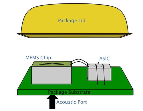
microphone die were ready for packaging. The separated device die were subsequently
packaged with a TO-8 package that was pre-drilled with a circular release hole. The release hole
allows the membrane to deflect and freely push air out the opening, thereby reducing the
deleterious effect of squeeze film damping.
3. Acoustic Testing
We evaluated the performance of a PZT microphone by placing a packaged microphone die into
an electrical test chamber (as seen in figure 5) with rubber grommet seals to prevent outside
noise interference. An acrylic cap was placed on top the packaged microphone die, and a Tygon2
tube was attached between the acrylic cap and the tube driver assembly. The acoustic test
chamber was configured with BNC3 mounts for electrical connection and a 1/8-inch inner
diameter (ID) nozzle for connecting to the Tygon tube from the signal source.
2 Tygon® is a registered trademark of Saint Gobain Performance Plastics.
3 not an acronym.
7
Figure 5. Images of the acoustic test chamber used for testing the PZT microphone.
(The BNC mounts provide electrical contact to the packaged microphone whereas
the acrylic plate on top provides a connection for the acoustic tube.)
Two different sound sources were used to characterize the performance of the PZT microphones.
The first source was an ACO4 Pacific electromagnetic source outputting a 1-kHz tone of either
94 dB or 104 dB. The second sound source was a B&K4 Pistonphone producing a 124-dB tone
at either 250 Hz or 325 Hz. As seen schematically in figure 6, the generated acoustic wave was
detected simultaneously by both a B&K4 calibrated microphone and the PZT microphone. The
data were collected with Labview software and subsequently analyzed with a MATLAB5
algorithm. To improve output signal from the PZT microphones, a Stanford Research Systems
4330 operational amplifier was added during the measurements.
4 not an acronym.
5 MATLAB® is a registered trademark of the Math Works.
8
Network
Analyzer
B&K
Mic
MEMS
Mic
Figure 6. Schematic representation of experimental test
setup for analysis of the PZT and calibrated
B&K microphones.
4. Results and Discussion
PZT membrane microphones with a diameter from 500 to 2000 μm were successfully fabricated
with two main designs initially focused upon. The first consisted of a PZT sensor covering the
central 80% of the released diaphragm while the second consisted of a PZT sensor covering the
outer 20% of the released diaphragm (see figures 7a and 7b, respectively). By reducing the
coverage of the PZT, a maximum output signal can be obtained by the combination of the
contribution from conflicting strain responses of a deflecting membrane. The 80/20 break down
of the two microphones was chosen because the inflection point in the strain response of a
deflecting membrane lies near this location. For each of the two choices, the PZT has been
removed from outside the sensor region.
9
a)
b)
Figure 7. (a) Optical surface micrograph of a PZT membrane
actuator with center 80% electroded and (b) optical
surface micrograph of a PZT actuator with outer
20% electroded.
Scanning electron micrographs in figure 8a illustrate the Bosch etch used to create the released
membrane. The resultant membrane structure consists of an overall positive stress gradient
resulting in a planar released surface as depicted in figure 8b. The bumps on the surface of the
device die are the remnant gold wire bonds. The last image in figure 8 shows the oxide
passivation around the perimeter of the PZT sensor as well as the Ti/Au contact strap.
500 μm
500 μm
Pt on
PZT
Ti/Pt
Top
Contact
Pt on
PZT
Ti/Pt
Top
Contact
10
a)
b)
c)
Figure 8. (a) An SEM image of a silicon DRIE release,
(b) SEM image of the surface profile of a released
membrane, and (c) SEM image illustrating the
SiO2 passivation.
Si DRIE Etch
Hole
Ti/Au
SiO2
Passivation
11
To assess the performance of the PZT membranes, the packaged die were first analyzed with a
Polytec scanning laser Doppler vibrometer so that the resonance characteristics could be
obtained. With a pseudorandom 1-Vp-p input signal with a 1-Voffset, the frequency response and
resonant mode shapes can be obtained for each of the diaphragms tested (see figure 9). Testing
of various sized membranes confirmed that when driven as actuators, they exhibit a classic 1/r
frequency dependence, in which r is the membrane radius, thereby proving that the microphones
operate as membranes and not as clamped plates (see figure 10).
a)
b)
0.2
0.4
0.6
0.8
1
100 200 300 400 500
Velocity (mm/s)
Frequency (kHz)
Figure 9. Laser Doppler vibrometry (LDV) results (a) mode shapes of fundamental
and third harmonic vibration and (b) frequency response from a 500-μm
diameter membrane with 80% sensor coverage.
0 500 nm
12
0 100
1 102
2 102
3 102
4 102
0 1000 2000 3000 4000 5000
Resonant Frequency (kHz)
1/Radius (m-1)
Linear Fit
Figure 10. Resonant frequency versus the inverse membrane
radius confirming membrane behavior rather than
clamped plate behavior of the PZT microphones.
The acoustic response of the microphones was plotted on a power (dB·V) versus frequency plot
after a fast Fourier transform (FFT) was performed on the voltage output from each sensor.
Typical plots generated for both sound sources are seen in figures 11a and 11b for a 750-μm
diameter microphone with 20% sensor coverage. The PZT microphones performed well in these
early experiments with magnitudes not too dissimilar from the B&K microphone. A clear
distinction between the PZT and B&K output was the amount of noise in the PZT response. One
side effect of using an unmatched amplifier was the unintentional amplification of the noise in
both the data acquistion as well as chamber losses. The noise amplification was also evident in
the 60 Hz harmonics present in figure 11 at 300 Hz and 1020 Hz. Although the noise floor is
amplified, it remains in the low to mid 10-6 V range whereas the noise floor for the B&K
microphone is 10-7 V.
13
a)
b)
Figure 11. Acoustic response of a B&K and a 750-μm diameter
PZT MEMS microphone with 20% sensor coverage for
(a) B&K Pistonphone 250-Hz tone at 124 dB and (b) ACO
Pacific 1-kHz tone at 104 dB.
An examination of the acoustic output from the PZT microphone produced an unamplified
sensitivity of 97.9 to 920 nV/Pa, depending on the size and configuration of the microphone.
This sensitivity falls far short from the predicted values that should range in the mid to high
microvolt per Pascal. The plot in figure 12 compares the predicted sensitivities against the
experimentally determined values including the amplifier. The amplified sensitivities were
plotted for ease of viewing both values. Each curve follows a radius squared relationship as
expected from the area term in the sensitivity equation. Unfortunately, the experimental values
do not possess the same multiplicative constant for increasing radius. Even with low sensitivities
of the PZT microphone, they exhibit a current limit of detection of ~ 50 dB SPL, which can
make the sensor viable as a remote acoustic sensor and useful in the preliminary testing of a
MEMS photo-acoustic sensor.
14
0 100
5 102
1 103
2 103
2 103
200 400 600 800 1000 1200
PZT (80% coverage)
PZT (20% coverage)
Predicted (80% coverage)
Predicted (20% coverage)
Sensitivity (μV/Pa)
Radius (μm)
Figure 12. Sensitivity versus radius of microphone including
both predicted values and the amplified experimental
results for the 20% and 80% coverage sensors.
There are several potential possibilities for the difference between predicted and experimental
values. One important characteristic to the predicted values concerns the assumption of zero
residual stress. It is well known from previous research efforts that a composite PZT thin film
actuator possesses a wide variety of residual stress values with the overall gradient determining
the behavior of the final device. As previously stated with figure 7, a planar-released membrane
indicates a positive residual stress gradient in the composite. In addition to the residual stress
assumption, the sensitivity equation also assumes a minimal load capacitance. There is
definitely a finite load capacitance in the electrical setup, especially considering the impedance
mismatch between the PZT sensor and the SRS operational amplifier (op-amp) and the
extraordinarily long connection cables. The final assumption with the sensitivity equation is
proper match of both the acoustic and electrical domains. Even though there is a open cavity in
the TO-5 package, there is an acoustic mismatch between the DRIE release via hole and the open
air cavity of the test chamber.
Another possible reason for the diminished output from the PZT microphones was resolved upon
investigation of the dielectric and ferroelectric properties of the devices. The dielectric
properties of the microphones were good with dielectric constants of 1021 ± 55 and a dielectric
loss of 3.5% ± 1%. Unfortunately, the ferroelectric hysteresis loops exhibited a pinched
hysteresis loop indicative on a non-optimal PZT thin film and may lead to diminished
piezoelectric properties (see figure 13). It is true that some of the normal hysteretic response can
be achieved with poling but in order to fully remove the effect of the pinched loop, a thermal
poling process is required. The packaged microphones were unable to undergo a thermal poling
process due at the time of this investigation.
15
Figure 13. Abnormal polarization electric field
hysteresis loop for a 1000-μm diameter
PZT microphone.
Besides optimizing the material properties and the acoustic and impedance matches, one
possibility for increasing the sensitivity is using electrode shaping and/or design. Combining the
output signal from the inner and outer regions of a deflecting membrane can be extremely
beneficial to the performance of a membrane. As presented by Kim (9), differential summation
from different regions of the acoustic sensor can be used to optimize the voltage output from a
piezoelectric microphone while minimizing the effects of increased capacitance with sensor size.
Our first attempts examine the combined output from a PZT sensor with both the outer 20% and
inner 75% covered with PZT (see figure 14).
Figure 14. Optical micrograph of a
80/20 combined acoustic
sensor.
Pt on
PZT
Ti/Pt
Top
Contact
Ti/Pt
16
5. Conclusion
Initial research successfully fabricated a piezoelectric microphone for acoustic sensing. The PZT
microphones were shown to perform well up to their mechanical resonant frequency and may
provide a low power means of detecting acoustic signals. These initial microphones exhibit a
sensitivity of 97.9 to 920 nV/Pa. Although these values are lower than predicted performance,
further modifications of the microphone, acoustic and electric impedance matching, and
predicting equations were presented as a means to further enhance the development of a PZT
MEMS-based microphone.
17
6. References
1. Scheeper, P. R.; van der Donk, A.G.H.; Olthuis, W.; Bergveld, P. A Review of Silicon
Microphones. Sens. Act. A 1994, 44, 1-11.
2. Fraim, F. W.; Murphy, P. V. Miniature Electret Microphones. J. Audio Eng. Soc. 1970, 18,
511-7.
3. Hohm, D.; Hess, G. A Subminiature Condenser Microphone with Silicon Nitride Meembran
and Silicon Back Plate. J. Acoust. Soc. Am. 1989, 85, 476-80.
4. Sprenkels, A. J.; Groothengel, R. A.; Verloop, A. J.; Bergveld, P. Development of an
Electret Microphone in Silicon. Sens. Act A 1989, 17, 509-12.
5. Schellin, R.; Hess, G. A Silicon Subminiature Microphone based on Piezoresistive
Polysilicon Strain Gauges. Sens. Act. A 1992, 32, 555-9.
6. Shellin, R.; Strecker, M.; Nothelfer, U.; Schuster, G. Low Pressure Acoustic Sensors for
Airborne Sound with Piezoresitive Monocrystalline Silicon and Electrochemically Etched
Diaphragms. Sens. Act. A 1995, 46-7, 156-60.
7. Arnold, D.; Gururaj, S.; Bhardwaj, S.; Nishida, T.; Sheplak, M. A Piezoresisitive
Microphone for Aeroacoustic Measurements. Proc. 2001 ASME Intern. Mech. Eng. Cong.
Expos., New York, Nov. 2001.
8. Royer, M.; Holmen, J. O.; Wurm, M. A.; Aadland, O. S.; Glenn, M. ZnO on Si Integrated
Acoustic Sensor. Sens. Act. A. 1983, 4, 357-62.
9. Kim, E. S. Integrated Microphone with CMOS circuits on a Single Chip. Ph. D dissertation,
EECS Dept., Univ. of Cal., Berkeley, May 1990.
10. Reid, R.; Kim, E.; Hong, D.; Muller, R. Piezoelectric Microphone with On-Chip CMOS
Circuits. J. MEMS 1993, 2, 111-20.
11. Pellegrino, P.; Polcawich, R. Advancement of a MEMS Photoacoustic Chemical Sensor.
submitted to SPIE Aerosense Chemical and Biological Sensing IV 2003, 5085.
12. Pellegrino, P.; Polcawich R. Evaluation of a MEMS Photoacoustic Sensor. submitted to
2002 Joint Service Scientific Conference Chemical Biological Defense Research, Hunt
Valley.
18
13. http://www.memsnet.org/material/zincoxideznofilm/
14. Budd, K. D.; Dey, S. K.; Payne, D. A. Sol-Gel Processing of PbTiO3, PbZrO3, PZT, and
PLZT Thin Films. Brit. Cer. Proc. 1985, 36, 107-21.
15. Laermer, F.; Schilp, A. Method of Anisotropically Etching Silicon. US-Patent No.
55018893.
19
Distribution List
ADMNSTR
DEFNS TECHL INFO CTR
ATTN DTIC-OCP (ELECTRONIC COPY)
8725 JOHN J KINGMAN RD STE 0944
FT BELVOIR VA 22060-6218
DARPA
ATTN IXO S WELBY
3701 N FAIRFAX DR
ARLINGTON VA 22203-1714
OFC OF THE SECY OF DEFNS
ATTN ODDRE (R&AT)
THE PENTAGON
WASHINGTON DC 20301-3080
US MILITARY ACDMY
MATHEMATICAL SCI CTR OF
EXCELLENCE
ATTN LTC T RUGENSTEIN
THAYER HALL RM 226C
WEST POINT NY 10996-1786
SMC/GPA
2420 VELA WAY STE 1866
EL SEGUNDO CA 90245-4659
US ARMY ARDEC
ATTN AMSTA-AR-TD
BLDG 1
PICATINNY ARSENAL NJ 07806-5000
COMMANDING GENERAL
US ARMY AVN & MIS CMND
ATTN AMSAM-RD W C MCCORKLE
REDSTONE ARSENAL AL 35898-5000
HICKS & ASSOC INC
ATTN G SINGLEY III
1710 GOODRICH DR STE 1300
MCLEAN VA 22102
PALISADES INST FOR RSRCH SVC INC
ATTN E CARR
1745 JEFFERSON DAVIS HWY STE 500
ARLINGTON VA 22202-3402
DIRECTOR
US ARMY RSRCH LAB
ATTN AMSRD-ARL-RO-D JCI CHANG
ATTN AMSRD-ARL-RO-EN W D BACH
PO BOX 12211
RESEARCH TRIANGLE PARK NC 27709
US ARMY RSRCH LAB
ATTN AMSRD-ARL-CI-OK-T TECHL
PUB (2 COPIES)
ATTN AMSRD-ARL-CI-OK-TL TECHL
LIB (2 COPIES)
ATTN AMSRD-ARL-D J M MILLER
ATTN AMSRD-ARL-SE-RL
J PULSKAMP
ATTN AMSRD-ARL-SE-RL M DUBEY
ATTN AMSRD-ARL-SE-RL
P AMIRTHARAJ
ATTN AMSRD-AL-SE-RL
A WICKENDEN
ATTN AMSRD-AML-SE-RL E ZAKAR
(10 COPIES)
ATTN AMSRD-ARL-SE-RL
L CURRANO
ATTN AMSRD-ARL-SE-RL
R POLCAWICH (10 COPIES)
ATTN IMNE-AD-IM-DR MAIL &
RECORDS MGMT
ADELPHI MD 20783-1197
20
INTENTIONALLY LEFT BLANK.