https://en.wikipedia.org/wiki/Nanogenerator
Nanogenerator
From Wikipedia, the free encyclopedia
Nanogenerator is a technology that converts mechanical/thermal energy as produced by small-scale physical change into electricity. Nanogenerator has three typical approaches: piezoelectric, triboelectric, and pyroelectric nanogenerators. Both the piezoelectric and triboelectric nanogenerators can convert the mechanical energy into electricity. However, the pyroelectric nanogenerators can be used to harvest thermal energy from a time-dependent temperature fluctuation.
Contents
[hide]Piezoelectric nanogenerator[edit]
A piezoelectric nanogenerator is an energy harvesting device converting the external kinetic energy into an electrical energy based on the energy conversion by nano-structured piezoelectric material. Although its definition may include any types of energy harvesting devices with nano-structure converting the various types of the ambient energy (e.g. solar power and thermal energy), it is used in most of times to specifically indicate the kinetic energy harvesting devices utilizing nano-scaled piezoelectric material after its first introduction in 2006.[1]
Although still in the early stage of the development, it has been regarded as a potential breakthrough toward the further miniaturization of the conventional energy harvester, possibly leading the facile integration with the other types of energy harvester converting the different types of energy and the independent operation of mobile electronic devices with the reduced concerns for the energy source, consequently.[citation needed]
Mechanism[edit]
| This section does not cite any references or sources. (November 2013) |


The working principle of nanogenerator will be explained for 2 different cases: the force exerted perpendicular and parallel to the axis of the nanowire.
The working principle for the first case is explained by a vertically grown nanowire subjected to the laterally moving tip. When a piezoelectric structure is subjected to the external force by the moving tip, the deformation occurs throughout the structure. The piezoelectric effect will create the electrical field inside the nanostructure; the stretched part with the positive strain will exhibit the positive electrical potential, whereas the compressed part with the negative strain will show the negative electrical potential. This is due to the relative displacement of cations with respect to anions in its crystalline structure. As a result, the tip of the nanowire will have an electrical potential distribution on its surface, while the bottom of the nanowire is neutralized since it is grounded. The maximum voltage generated in the nanowire can be calculated by the following equation:[2]
![V_{\text{max}} = \pm \frac{3}{4(\kappa_0+\kappa)}[e_{\text{33}} - 2(1 + \nu) e_{\text{15}} - 2\nu e_{\text{31}}] \frac{a^3}{l^3} \nu_{\text{max}}](https://upload.wikimedia.org/math/5/a/9/5a945f06891de20911dd21f8f5f89cde.png)
, where κ0 is the permittivity in vacuum, κ is the dielectric constant, e33, e15 and e31 are the piezoelectric coefficients, ν is the Poisson ratio, a is the radius of the nanowire, l is the length of the nanowire and νmax is the maximum deflection of the nanowire's tip.
The electrical contact plays an important role to pump out charges in the surface of the tip. The schottky contact must be formed between the counter electrode and the tip of the nanowire since the ohmic contact will neutralize the electrical field generated at the tip. In order to form an effective schottky contact, the electron affinity(Ea) must be smaller than the work function(φ) of the metal composing the counter electrode. For the case of ZnO nanowire with the electron affinity of 4.5 eV, Pt (φ=6.1eV) is a suitable metal to construct the schottky contact. By constructing the schottky contact, the electrons will pass to the counter electrode from the surface of the tip when the counter electrode is in contact with the regions of the negative potential, whereas no current will be generated when it is in contact with the regions of the positive potential, in the case of n-type semiconductive nanostructure (p-type semiconductive structure will exhibit the reversed phenomenon since the hole is mobile in this case). The formation of the schottky contact also contributes to the generation of direct current output signal consequently.
For the second case, a model with a vertically grown nanowire stacked between the ohmic contact at its bottom and the schottky contact at its top is considered. When the force is applied toward the tip of the nanowire, the uniaxial compressive is generated in the nanowire. Due to the piezoelectric effect, the tip of the nanowire will have a negative piezoelectric potential, increasing the Fermi level at the tip. Since the electrons will then flow from the tip to the bottom through the external circuit as a result, the positive electrical potential will be generated at the tip. The schottky contact will barricade the electrons being transported through the interface, therefore maintaining the potential at the tip. As the force is removed, the piezoelectric effect diminishes, and the electrons will be flowing back to the top in order to neutralize the positive potential at the tip. The second case will generate alternating current output signal.
Geometrical configuration[edit]
Depending on the configuration of piezoelectric nanostructure, the most of the nanogenerator can be categorized into 3 types: VING, LING and "NEG". Still, there is a configuration that do not fall into the aforementioned categories, as stated in other type.
Vertical nanowire Integrated Nanogenerator (VING).

VING is a 3-dimensional configuration consisting of a stack of 3 layers in general, which are the base electrode, the vertically grown piezoelectric nanostructureand the counter electrode. The piezoelectric nanostructure is usually grown from the base electrode by various synthesizing techniques, which are then integrated with the counter electrode in full or partial mechanical contact with its tip.
After Professor Zhong Lin Wang of the Georgia Institute of Technology has introduced a basic configuration of VING in 2006 where he used a tip of atomic force microscope (AFM) to induce the deformation of a single vertical ZnO nanowire, the first development of VING is followed in 2007.[3] The first VING utilizes the counter electrode with the periodic surface grating resembling the arrays of AFM tip as a moving electrode. Since the counter electrode is not in full contact with the tips of the piezoelectric nanowire, its motion in-plane or out-of-plane occurred by the external vibration induces the deformation of the piezoelectricnanostructure, leading to the generation of the electrical potential distribution inside each individual nanowire. It should be noted that the counter electrode is coated with the metal forming the schottky contact with the tip of the nanowire, where only the compressed portion of piezoelectric nanowire would allow the accumulated electrons pass through the barrier between its tip and the counter electrode, in case of n-type nanowire. The switch-on and –off characteristic of this configuration shows its capability of generating direct current generation without any requirement for the external rectifier.
In VING with partial contact, the geometry of the counter electrode plays an important role. The flat counter electrode would not induce the sufficient deformation of the piezoelectric nanostructures, especially when the counter electrode moves by in-plane mode. After the basic geometry resembling the array of AFM tips, a few other approaches have been followed for facile development of the counter electrode. Professor Zhong Lin Wang's group have generated counter electrode composed of ZnO nanorods utilizing the similar technique used for synthesizing ZnO nanowire array. Professor Sang-Woo Kim's group ofSungkyunkwan University (SKKU) and Dr. Jae-Young Choi's group of Samsung Advanced Institute of Technology (SAIT) in South Korea introduced bowl-shaped transparent counter electrode by combininganodized aluminum and the electroplating technology.[4] They also have developed the other type of the counter electrode by using networked single-walled carbon-nanotube (SWNT) on the flexible substrate, which is not only effective for energy conversion but also transparent.[5]
The other type of VING has been also suggested. While it shares the identical geometric configuration with the aforementioned, such a VING has full mechanical contact between the tips of the nanowires and the counter electrode.[6] This configuration is effective for application where the force is exerted in the vertical direction (toward the c axis of the piezoelectric nanowire), and it generates alternating current (AC) unlike VINGs with partial contact.
Lateral nanowire Integrated Nanogenerator (LING).

LING is a 2-dimensional configuration consisting of three parts: the base electrode, the laterally grown piezoelectric nanostructure and the metal electrode for schottky contact. In most of cases, the thickness of the substrate film is much thicker than the diameter of the piezoelectric nanostructure, so the individual nanostructure is subjected to the pure tensile strain.
LING is an expansion of single wire generator (SWG), where a laterally aligned nanowire is integrated on the flexible substrate. SWG is rather a scientific configuration used for verifying the capability of electrical energy generation of a piezoelectric material and is widely adopted in the early stage of the development.
As of VINGs with full mechanical contact, LING generates AC electrical signal. The output voltage can be amplified by constructing an array of LING connected in series on the single substrate, leading the constructive addition of the output voltage. Such a configuration may lead to the practical application of LING for scavenging large-scale power, for example, wind or ocean waves.
Nanocomposite Electrical Generators (NEG).

"NEG" is a 3-dimensional configuration consisting three main parts: the metal plate electrodes, the vertically grown piezoelectric nanostructure and the polymer matrix which fills in between in the piezoelectricnanostructure.
NEG was introduced by Momeni et al.[7] It was shown that NEG has a higher efficiency compared to original nanogenerator configuration which a ZnO nanowire will be bended by an AFM tip. It is also shown that it provides an energy source with higher sustainability.
Other type. The fabric-like geometrical configuration has been suggested by Professor Zhong Lin Wang in 2008. The piezoelectric nanowire is grown vertically on the two microfibers in its radial direction, and they are twined to form a nanogenerator.[8] One of the microfibers is coated with the metal to form a schottky contact, serving as the counter electrode of VINGs. As the movable microfiber is stretched, the deformation of the nanostructure occurs on the stationary microfiber, resulting in the voltage generation. Its working principle is identical to VINGs with partial mechanical contact, thus generating DC electrical signal.
Materials[edit]
Among various piezoelectric materials studied for the nanogenerator, many of the researches have been focused on the materials with wurtzite structure such as ZnO, CdS[9] and GaN.[10] The greatest advantage of theses material arises from the facile and cost-effective fabrication technique, hydrothermal synthesis. Since the hydrothermal synthesis can be conducted in a low temperature environment under 100°C in addition to vertical and crystalline growth, these materials can be integrated in various substrates with reduced concern for its physical characteristics such as a melting temperature.
Endeavors for enhancing the piezoelectricity of the individual nanowire also led to the development of other piezoelectric materials based on Wurtzite structure. Professor Zhong Lin Wang of Georgia Institute of Technology introduced p-type ZnO nanowire.[11] Unlike the n-type semiconductive nanostructure, the mobile particle in p-type is a hole, thus the schottky behavior is reversed from that of n-type case; the electrical signal is generated from the portion of the nanostructure where the holes are accumulated. It is experimentally proved that p-type ZnO nanowire can generate the output signal near 10 times that of n-type ZnO nanowire.
From the idea that the material with perovskite structure is known to have more effective piezoelectric characteristic compared to that with wurtzite structure, Barium titanate (BaTiO3) nanowire has been also studied by Professor Min-Feng Yu of University of Illinois at Urbana Champaign.[12] The output signal is found to be more than 16 time that from a similar ZnO nanowire.
Professor Liwei Lin of University of California at Berkeley has suggested that PVDF can be also applied to form a nanogenerator.[13] Being a polymer, PVDF utilizes a near-field electrospinning for its fabrication, which is rather a different technique compared to other materials. The nanofiber can be directly written on the substrate controlling the process, and this technique is expected to be applied for forming self-powered textile based on nanofiber.
Comparison of the reported materials by 2010 is given in the following table.
| Material | Type | Geometry | Output voltage | Output power | Synthesis | Researched at |
|---|---|---|---|---|---|---|
| ZnO (n-type) | Wurtzite | D: ~100 nm, L: 200~500 nm | VP=~9 mV @ R=500 MΩ | ~0.5 pW per cycle (estimated) | CVD, hydrothermal process | Georgia Tech. |
| ZnO (p-type) | Wurtzite | D: ~50 nm, L: ~600 nm | VP=50~90 mV @ R=500 MΩ | 5~16.2 pW per cycle (calculated) | CVD | Georgia Tech. |
| ZnO-ZnS | Wurtzite (Heterostructure) | Not stated | VP=~6 mV @ R=500 MΩ | ~0.1 pW per cycle (calculated) | Thermal evaporation and etching | Georgia Tech. |
| GaN | Wurtzite | D: 25~70 nm, L: 10~20 μm | Vavg=~20 mV, Vmax=~0.35 V@ R=500 MΩ | ~0.8 pW per cycle (average, calculated) | CVD | Georgia Tech.[10] |
| CdS | Wurtzite | D: ~100 nm, L: 1 μm | VP=~3 mV | Not stated | PVD, Hydrothermal Process | Georgia Tech.[9] |
| BaTiO3 | Pervoskite | D: ~280 nm, L: ~15 μm | VP=~25 mV @ R=100 MΩ | ~0.3 aJ per cycle (stated) | High temperature chemical reaction | UIUC[12] |
| PVDF | Polymer | D: 0.5~6.5 μm, L: 0.1~0.6 mm | VP=5~30 mV | 2.5 pW~90 pW per cycle (calculated) | Electro spinning | UC Berkeley[13] |
Applications[edit]
Nanogenerator is expected to be applied for various applications where the periodic kinetic energy exists, such as wind and ocean waves in a large scale to the muscle movement by the beat of a heart or inhalation of lung in a small scale. The further feasible applications are as follows.
Self-powered nano/micro devices. One of the feasible applications of nanogenerator is an independent or a supplementary energy source to nano/micro devices consuming relatively low amount of energy in a condition where the kinetic energy is supplied continuously. One of example has been introduced by Professor Zhong Lin Wang's group in 2010 by the self-powered pH or UV sensor integrated VING with an output voltage of 20~40 mV onto the sensor.
Still, the converted electrical energy is relatively small for operating nano/micro devices; therefore the range of its application is still bounded as a supplementary energy source to the battery. The breakthrough is being sought by combining the nanogenerator with the other types of energy harvesting devices, such as solar cell or biochemical energy harvester.[14][15] This approach is expected to contribute to the development of the energy source suitable for the application where the independent operation is crucial, such asSmartdust.
Smart Wearable Systems. The outfit integrated or made of the textiles with the piezoelectric fiber is one of the feasible applications of the nanogenerator. The kinetic energy from the human body is converted to the electrical energy through the piezoelectric fibers, and it can be possibly applied to supply the portable electronic devices such as health-monitoring system attached with the Smart Wearable Systems. The nanogenerator such as VING can be also easily integrated in the shoe employing the walking motion of human body.
Another similar application is a power-generating artificial skin. Professor Zhong Lin Wang's group has shown the possibility by generating AC voltage of up to 100 mV from the flexible SWG attached to the running hamster.[16]
Transparent and Flexible Devices. Some of the piezoelectric nanostructure can be formed in various kinds of substrates, such as flexible and transparent organic substrate. The research groups in SKKU (Professor Sang-Woo Kim's group) and SAIT (Dr. Jae-Young Choi's group) have developed the transparent and flexible nanogenerator which can be possibly used for self-powered tactile sensor and anticipated that the development may be extended to the energy-efficient touch screen devices. Their research focus is being extended to enhance the transparency of the device and the cost-effectiveness by substituting Indium-Tin-Oxide (ITO) electrode with a graphene layer.[17]
Implantable Telemetric Energy Receiver. The nanogenerator based on ZnO nanowire can be applied for implantable devices since ZnO not only is bio-compatible but also can be synthesized upon the organic substrate, rendering the nanogenerator bio-compatible in overall. The implantable device integrated with the nanogenerator can be operated by receiving the external ultrasonic vibration outside the human body, which is converted to the electrical energy by the piezoelectric nanostructure.
Triboelectric nanogenerator[edit]

A triboelectric nanogenerator is an energy harvesting device that converts the external mechanical energy into electricity by a conjunction of triboelectric effect and electrostatic induction. This new type of nanogenerator was firstly demonstrated in Prof. Zhong Lin Wang's group at Georgia Institute of Technology in the year of 2012.[18] As for this power generation unit, in the inner circuit, a potential is created by the triboelectric effect due to the charge transfer between two thin organic/inorganic films that exhibit opposite tribo-polarity; in the outer circuit, electrons are driven to flow between two electrodes attached on the back sides of the films in order to balance the potential. Since the most useful materials for TENG are organic, it is also named organic nanogenerator, which is the first of using organic materials for harvesting mechanical energy.
Ever since the first report of the TENG in January 2012, the output power density of TENG has been improved for five orders of magnitude within 12 months. The area power density reaches 313 W/m2, volume density reaches 490 kW/m3, and a conversion efficiency of ~60% has been demonstrated. Besides the unprecedented output performance, this new energy technology also has a number of other advantages, such as low cost in manufacturing and fabrication, excellent robustness and reliability, environmental-friendly, and so on. The triboelectric nanogenerator can be applied to harvest all kind mechanical energy that is available but wasted in our daily life, such as human motion, walking, vibration, mechanical triggering, rotating tire, wind, flowing water and more.[19]
The triboelectric nanogenerator has three basic operation modes: vertical contact-separation mode, in-plane sliding mode, and single-electrode mode. They have different characteristics and are suitable for different applications
Basic modes and mechanisms[edit]
Vertical Contact-Separation Mode

The working mechanism of the triboelectric nanogenerator can be described as the periodic change of the potential difference induced by the cycled separation and re-contact of the opposite triboelectric charges on the inner surfaces of the two sheets. When a mechanical agitation is applied onto the device to bend or press it, the inners surfaces of the two sheets will get into close contact and the charge transfer will begin, leaving one side of the surface with positive charges and the other with negative charges. This is just the triboelectric effect. When the deformation is released, the two surfaces with opposite charges will separate automatically, so that these opposite triboelectrc charges will generate an electric field in between and thus induce a potential difference across the top and bottom electrodes. In order to screen this potential difference, the electrons will be driven to flow from one electrode to the other through the external load. The electricity generated in this process will continue until the potentials of the two electrodes get back to even again. Subsequently, when the two sheets are pressed towards each other again, the triboelectric-charge-induced potential difference will begin to decrease to zero, so that the transferred charges will flow back through the external load, to generate another current pulse in the opposite direction. When this periodic mechanical deformation lasts, the alternating current (AC) signals will be continuously generated.[20][21]
As for the pair of materials getting in contact and generating triboelectric charges, at least one of them need to be an insulator, so that the triboelectric charges cannot be conducted away but will remain on the inner surface of the sheet. Then, these immobile triboelectric charges can induce AC electricity flow in the external load under the periodic distance change.
Lateral Sliding Mode
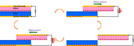
There are two basic friction processes: normal contact, and lateral sliding. We demonstrated here a TENG that is designed based on the in-plane sliding between the two surfaces in lateral direction.[22] With an intensive triboelectrification facilitated by sliding friction, a periodic change in the contact area between two surfaces leads to a lateral separation of the charge centers, which creates a voltage drop for driving the flow of electrons in the external load. The sliding-induced electricity generation mechanism is schematically depicted in the figure. In the original position, the two polymeric surfaces fully overlap and intimately contact with each other. Because of the large difference in the ability to attract electrons, the triboelectrification will leave one surface with net positive charges and the other with net negative charges with equal density. Since the tribo-charges on the insulators will only distribute in the surface layer and will not be leaked out for an extended period of time, the separation between the positively charged surface and negatively charged surface is negligible at this overlapping position, and thus there will be little electric potential drop across the two electrodes. Once the top plate with the positively charged surface starts to slide outward, the in-plane charge separation is initiated due to the decrease in contact surface area. The separated charges will generate an electric field pointing from the right to the left almost parallel to the plates, inducing a higher potential at the top electrode. This potential difference will drive a current flow from the top electrode to the bottom electrode in order to generate an electric potential drop that cancels the tribo-charge-induced potential. Because the vertical distance between the electrode layer and the tribo-charged polymeric surface is negligible compared to the lateral charge separation distance, the amount of the transferred charges on the electrodes approximately equals to the amount of the separated charges at any sliding displacement. Thus, the current flow will continue with the continuation of the ongoing sliding process that keeps increasing the separated charges, until the top plate fully slides out of the bottom plate and the tribo-charged surfaces are entirely separated. The measured current should be determined by the rate at which the two plates are being slid apart. Subsequently, when the top plate is reverted to slide backwards, the separated charges begins to get in contact again but no annihilation due to the insulator nature of the polymer materials. The redundant transferred charges on the electrodes will flow back through the external load with the increase of the contact area, in order to keep the electrostatic equilibrium. This will contribute to a current flow from the bottom electrode to the top electrode, along with the second half cycle of sliding. Once the two plates reach the overlapping position, the charged surfaces get into fully contact again. There will be no transferred charges left on the electrode, and the device returns to the first state. In this entire cycle, the processes of sliding outwards and inwards are symmetric, so a pair of symmetric alternating current peaks should be expected.
The mechanism of in-plane charge separation can work in either one directional sliding between two plates[23] or in rotation mode.[24] In the sliding mode, introducing linear grating or circular segmentation on the sliding surfaces is an extremely efficient means for energy harvesting. With such structures, two patterned triboelectric surfaces can get to fully mismatching position through a displacement of only a grating unit length rather than the entire length of the TENG so that it dramatically increase the transport efficiency of the induced charges.
Single-Electrode Mode

A single-electrode-based triboelectric nanogenerator is introduced as a more practical and feasible design for some applications such as fingertip-driven triboelectric nanoagenerator.[25][26] The working principle of the single-electrode TENG is schematically shown in the figure by the coupling of contact electrification and electrostatic induction. In the original position, the surfaces of skin and PDMS fully contact with each other, resulting in charge transfer between them. According to the triboelectric series, electrons were injected from the skin to the PDMS since the PDMS is more triboelectrically negative than skin, which is the contact electrification process. The produced triboelectric charges with opposite polarities are fully balanced/screened, leading to no electron flow in the external circuit. Once a relative separation between PDMS and skin occurs, these triboelectric charges cannot be compensated. The negative charges on the surface of the PDMS can induce positive charges on the ITO electrode, driving free electrons to flow from the ITO electrode to ground. This electrostatic induction process can give an output voltage/current signal if the distance separating between the touching skin and the bottom PDMS is appreciably comparable to the size of the PDMS film. When negative triboelectric charges on the PDMS are fully screened from the induced positive charges on the ITO electrode by increasing the separation distance between the PDMS and skin, no output signals can be observed, as illustrated. Moreover, when the skin was reverted to approach the PDMS, the induced positive charges on the ITO electrode decrease and the electrons will flow from ground to the ITO electrode until the skin and PDMS fully contact with each other again, resulting in a reversed output voltage/current signal. This is a full cycle of electricity generation process for the TENG in contact-separation mode.
Applications[edit]
TENG is a physical process of converting mechanical agitation to an electric signal through the triboelectrification (in inner circuit) and electrostatic induction processes (in outer circuit). This basic process has been demonstrated for two major applications. The first application is energy harvesting with a particular advantage of harvesting mechanical energy. The other application is to serve as a self-powered active sensor, because it does not need an external power source to drive.
Harvesting vibration energy
| This article or section may have been copied and pasted from http://www.nanoscience.gatech.edu/paper/2013/13_ACSN_08.pdf (DupDet · CopyVios), possibly in violation of Wikipedia's copyright policy. Please remedy this by editing this article to remove any non-free copyrighted content and attributing free content correctly, or flagging the content for deletion. Please be sure that the source of the copyright violation is not itself a Wikipedia mirror. (November 2013) |
Vibration is one of the most popular phenomena in our daily life, from walking, voices, engine vibration, automobile, train, aircraft, wind and many more. It exists almost everywhere and at all the time. Harvesting vibration energy is of great value especially for powering mobile electronics. The following Based on the fundamental principles of triboelectric nanogenerators, various technologies have been demonstrated for harvesting vibration energy. This application of triboelectric nanogenerator has been demonstrated in the following aspects: 1. Cantilever-based technique is a classical approach for harvesting mechanical energy, especially for MEMS. By designing the contact surface of a cantilever with the top and bottom surfaces during vibration, TENG has been demonstrated for harvesting ambient vibration energy based on the contact-separation mode.[27] 2. To harvest the energy from a backpack, we demonstrated a rationally designed TENG with integrated rhombic gridding, which greatly improved the total current output owing to the structurally multiplied unit cells connected in parallel.[28] 3. With the use of 4 supporing springs, a harmonic resonator-based TENG has been fabricated based on the resonance induced contact-separation between the two triboelectric materials, which has been used to harvest vibration energy from an automobile engin, a sofa and a desk.[29] 4. Recently, a three-dimensional triboelectric nanogenerator (3D-TENG) has been designed based on a hybridization mode of conjunction the vertical contact-separation mode and the in-plane sliding mode.36 The innovative design facilitates harvesting random vibration energy in multiple directions over a wide bandwidth. The 3-D TENG is designed for harvesting ambient vibration energy, especially at low frequencies, under a range of conditions in daily life, thus, opening the applications of TENG in environmental/infrastructure monitoring, charging portable electronics and internet of things.
Harvesting energy from human body motion
Since there is abundant mechanical energy generated on human bodies in people's everyday life, we can make use of the triboelectric nanogenerator to convert this amount of mechanical energy into electricity, for charging portable electronics and biomedical applications. This will help to greatly improve the convenience of people's life and expand the application of the personal electronics. A packaged power-generating insole with built-in flexible multi-layered triboelectric nanogenerators has been demonstrated, which enable harvesting mechanical pressure during normal walking. The TENG used here relies on the contact-separation mode and is effective in responding to the periodic compression of the insole. Using the insole as a direct power source, we develop a fully packaged self-lighting shoe that has broad applications for display and entertainment purposes. A TENG can be attached to the inner layer of a shirt for harvesting energy from body motion. Under the generally walking, the maximum output of voltage and current density are up to 17 V and 0.02 μA/cm2, respectively. The TENG with a single layer size of 2 cm×7 cm×0.08 cm sticking on the clothes was demonstrated as a sustainable power source that not only can directly light up 30 light-emitting diodes (LEDs), but also can charge a lithium ion battery by persistently clapping clothes.
Self-powered active strain/force sensors
An triboelectric nanogenerator automatically generates an output voltage and current once it is mechanically triggered. The magnitude or the output signal signifies the impact of the mechanical deformation and its time-dependent behavior. This is the basic principle of the TENG can be applied as a self-powered pressure sensor. The voltage-output signal can reflect the applied pressure induced by a droplet of water. All types of TENGs have a high sensitivity and fast response to the external force and show as a sharp peak signal. Furthermore, the response to the impact of a piece of feather (20 mg, ~0.4 Pa in contact pressure) can be detected. The sensor signal can delicately show these details of the entire process. The existing results show that our sensor can be applied for measuring the subtle pressure in real life.[30]
In a case that we make a matric array of the triboelectric nanogenerators, a large-area, and self-powered pressure map applied on a surface can be realized.[31] The response of the TENG array with local pressure was measured through a multi-channel measurement system. There are two types of output signals from the TENG: open circuit voltage and short circuit current. The Open circuit voltage is only dictated by the final configuration of the TENG after applying a mechanical triggering, so that it is a measure of the magnitude of the deformation, which is attributed to the static information to be provided by TENG. The output current depends on the rate at which the induced charge would flow, so that the current signal is more sensitive to the dynamic process of how the mechanical triggering is applied.
The active pressure sensor and the integrated sensor array based on the triboelectric effect have several advantages over conventional passive pressure sensors. First, the active sensor is capable of both static pressure sensing using the open-circuit voltage and dynamic pressure sensing using the short-circuit current, while conventional sensors are usually incapable of dynamic sensing to provide the loading rate information. Second, the prompt response of both static and dynamic sensing enables the revealing of details about the loading pressure. Third, the detection limit of the TENG for dynamic sensing is as low as 2.1 Pa, owing to the high output of the TENG. Fourth, the active sensor array presented in this work has no power consumption and could even be combined with its energy harvesting functionality for self-powered pressure mapping. Future works in this field involve the miniaturization of the pixel size to achieve higher spatial resolution, and the integration of the TEAS matrix onto fully flexible substrate for shape-adaptive pressure imaging.
Self-powered active chemical sensors
As for triboelectric nanogenerators, maximizing the charge generation on opposite sides can be achieved by selecting the materials with the largest difference in the ability to attract electrons and changing the surface morphology. In such a case, the output of the TENG depends on the type and concentration of molecules adsorbed on the surface of the triboelectric materials, which can be used for fabricating chemical and biochemical sensors. As an example, the performance of the TENG depends on the assembly of Au nanoparticles (NPs) onto the metal plate. These assembled Au NPs not only act as steady gaps between the two plates at strain free condition, but also enable the function of enlarging the contact area of the two plates, which will increase the electrical output of the TENG. Through further modification of 3-mercaptopropionic acid (3-MPA) molecules on the assembled Au NPs, the high-output nanogenerator can become a highly sensitive and selective nanosensor toward Hg2+ ions detection because of the different triboelectric polarity of Au NPs and Hg2+ ions. With its high sensitivity, selectivity and simplicity, the TENG holds great potential for the determination of Hg2+ ions in environmental samples. The TENG is a future sensing system for unreachable and access-denied extreme environments. As different ions, molecules, and materials have their unique triboelectric polarities, we expect that the TENG can become either an electrical turn-on or turn-off sensor when the analytes are selectively binding to the modified electrode surface. We believe this work will serve as the stepping stone for related TENG studies and inspire the development of TENG toward other metal ions and biomolecules such as DNA and proteins in the near future.[32]
Choice of materials and surface structures[edit]
Almost all materials known exhibit the triboelectrification effect, from metal, to polymer, to silk and to wood, almost everything. All of these materials can be candidates for fabricating TENGs, so that the materials choices for TENG are huge. However, the ability of a material for gaining/losing electron depends on its polarity. John Carl Wilcke published the first triboelectric series in a 1757 on static charges. A material towards the bottom of the series, when touched to a material near the top of the series, will attain a more negative charge. The further away two materials are from each other on the series, the greater the charge transferred. Beside the choice of the materials in the triboelectric series, the morphologies of the surfaces can be modified by physical techniques with the creation of pyramids-, square- or hemisphere-based micro- or nano-patterns, which are effective for enhancing the contact area and possibly the triboelectrification. However, the created bumpy structure on the surface may increase the friction force, which may possibly reduce the energy conversion efficiency of the TENG. Therefore, an optimization has to be designed for maximizing the conversion efficiency.
The surfaces of the materials can be functionalized chemically using various molecules, nanotubes, nanowires or nanoparticles, in order to enhance the triboelectrification effect. Surface functionalization can largely change the surface potential. The introduction of nanostructures on the surfaces can change the local contact characteristics, which may improve the triboelectrification. This will involve a large amount of studies for testing a range of materials and a range of available nanostructures.
Besides these pure materials, the contact materials can be made of composites, such embedding nanoparticles in polymer matrix. This not only changes the surface electrification, but also the permittivity of the materials so that they can be effective for electrostatic induction. Therefore, there are numerous ways for enhancing the performance of the TENG from the materials point of view. This gives an excellent opportunity for chemists and materials scientists to do extensive study both in the basic science and in practical application. In contrast, materials systems for solar cell and thermal electric, for example, are rather limited, and there are not very many choices for high performance devices.
Therefore, there are numerous ways for enhancing the performance of the TENG from the materials point of view. This gives an excellent opportunity for chemists and materials scientists to do extensive study both in the basic science and in practical application. In contrast, materials systems for solar cell and thermal electric, for example, are rather limited, and there are not very many choices for high performance devices.
Pyroelectric nanogenerator[edit]
A pyroelectric nanogenerator is an energy harvesting device converting the external thermal energy into an electrical energy by using nano-structured pyroelectric materials. Usually, harvesting thermoelectric energy mainly relies on the Seebeck effect that utilizes a temperature difference between two ends of the device for driving the diffusion of charge carriers.[33] However, in an environment that the temperature is spatially uniform without a gradient, such as in outdoor in our daily life, the Seebeck effect can not be used to harvest thermal energy from a time-dependent temperature fluctuation. In this case, the pyroelectric effect has to be the choice, which is about the spontaneous polarization in certain anisotropic solids as a result of temperature fluctuation.[34] The first pyroelectric nanogenerator was introduced by Prof. Zhong Lin Wang at Georgia Institute of Technology in 2012.[35] By harvesting the waste heat energy, this new type of nanogenerator has the potential applications such as wireless sensors, temperature imaging, medical diagnostics, and personal electronics.
Mechanism[edit]

The working principle of pyroelectric nanogenerator will be explained for 2 different cases: the primary pyroelectric effect and the secondary pyroelectric effect.
The working principle for the first case is explained by the primary pyroelectric effect, which describes the charge produced in a strain-free case. The primary pyroelectric effect dominates the pyroelectric response in PZT, BTO, and some other ferroelectric materials.[36] The mechanism is based on the thermally induced random wobbling of the electric dipole around its equilibrium axis, the magnitude of which increases with increasing temperature.[37] Due to thermal fluctuations under room temperature, the electric dipoles will randomly oscillate within a degree from their respective aligning axes. Under a fixed temperature, the total average strength of the spontaneous polarization form the electric dipoles is constant, resulting in no output of the pyroelectric nanogenerator. If we apply a change in temperature in the nanogenerator from room temperature to a higher temperature, the increase in temperature will result in that the electric dipoles oscillate within a larger degree of spread around their respective aligning axes. The total average spontaneous polarization is decreased due to the spread of the oscillation angles. The quantity of induced charges in the electrodes are thus reduced, resulting in a flow of electrons. If the nanogenerator is cooled instead of heated, the spontaneous polarization will be enhanced since the electric dipoles oscillate within a smaller degree of spread angles due to the lower thermal activity. The total magnitude of the polarization is increased and the amount of induced charges in the electrodes are increased. The electrons will then flow in an opposite direction.
For the second case, the obtained pyroelectric response is explained by the secondary pyroelectric effect, which describes the charge produced by the strain induced by thermal expansion. The secondary pyroelectric effect dominates the pyroelectric response in ZnO, CdS, and some other wurzite-type materials. The thermal deformation can induce a piezoelectric potential difference across the material, which can drive the electrons to flow in the external circuit. The output of the nanogenerator is associated with the piezoelectric coefficient and the thermal deformation of the materials. The output current I of the pyroelectric nanogenerators can be determined by the equation of I=pA(dT/dt), where p is the pyroelectric coefficient, A is the effective area of the NG, dT/dt is the rate of change in temperature.
Applications[edit]
Pyroelectric nanogenerator is expected[by whom?] to be applied for various applications where the time-dependent temperature fluctuation exists. One of the feasible applications of the pyroelectric nanogenerator is used as an active sensor, which can work without a battery. One example has been introduced by Professor Zhong Lin Wang's group in 2012 by using a pyroelectric nanogenerator as the self-powered temperature sensor for detecting a change in temperature, where the response time and reset time of the sensor are about 0.9 and 3 s, respectively.[38] In general, the pyroelectric nanogenerator gives a high output voltage, but the output current is small. It not only can be used as a potential power source, but also as an active sensor for measuring temperature variation.